Telephone Lines
Reprinted from "Crown Jewels of the Wire", June 1992, page 24
And Methods Of Constructing Them
Overhead And Underground.
by WALTER C. OWEN,
Consulting Telephone Engineer, Late District Manager And Engineer
National Telephone Company Limited.
1903.
(Reprint sent by Steve Corfidi, State College, PA, publishers Whittaker &
CO., London)
Medium Image (93 Kb)
Large Image (213 Kb)
CHAPTER VII.
INSULATORS.
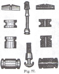
That the primary and all-important function of an " insulator"
is to insulate, and that to insulate is to isolate, is a fact which does not
appear to have been fully understood or appreciated by many telephone engineers in days gone by, or at least gave them
little concern, if one is to judge from the wholly inadequate and inefficient
means which they adopted. in order to insulate their wires, in the shape of
knobs, wheels, cones, rubber hooks, and similar devices (Fig. 77), and more
particularly the double shackle which was at one time most extensively employed.
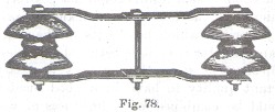
The Bright's shackle, or rather an inferior copy of it (Fig. 78), was
universally used by all the telephone companies exploiting the various portions
of the British Isles for many years, and its use was only finally abandoned, in
some cases very reluctantly, when the absolute necessity for a higher degree
of insulation than was obtainable by its use was imperative, consequent upon the
establishment of long trunk lines, and the substitution of metallic for single or earth line circuits.
So
long as the length of line to be spoken over was small, a very high standard
of insulation was not absolutely necessary in order to obtain a certain degree
of efficiency with an earth circuit telephone line; indeed, such a line will
often work better if there is a certain amount of leakage of current to earth
from it than it would if perfectly insulated, providing the leakage is
uniform in extent throughout its whole length. This is exemplified by the fact that speech over such a circuit is
often much clearer on a wet day than on a
fine and dry one.
Earth circuits have now however been almost entirely
superseded by metallic circuits, and the speaking limit is not confined within
the area of city boundaries, but has extended to many hundreds of miles. This result has been brought about
not owing to any great improvement in the instruments used, for they are practically still the same as
those first
employed, but to the much greater electrical efficiency of the lines, due very
largely to their more perfect insulation. Such results could not possibly have
been achieved by the use of the shackle, the principal and only merit of which lies
in its mechanical strength; as an insulator it is little better than useless.
Mechanical strength is a very necessary and important quality to have in a good insulator,
but it should he combined
with lightness of weight, and, above all, the highest degree of efficiency, as a
means of preventing the escape of current from a line wire to earth or to
another contiguous wire. These two latter qualities are certainly not possessed
by the Bright's shackle. It was therefore discarded in favor of insulators of the upright form, which at once
resulted in an enormous increase in the electrical efficiency of the lines
wherever used,
and decrease in the weight of the material.
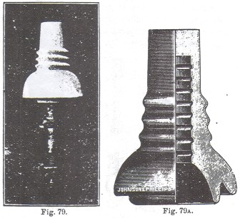
One of the first insulators specially designed to meet the necessities of the case was that
introduced by Mr. W. T. Langdon, the Superintendent of Telegraphs for the Midland
Railway Company, and very many thousands of this
pattern of insulator have been used by telephone administrations in all parts of
the world with excellent results, and it still remains one of the best of its
kind obtainable. This form of insulator, which is commonly known as a. "Langdon," is illustrated in Figs.
79 and 79A.
About the same time Mr. A. R. Bennett, now consulting telephone engineer to
the Glasgow and several other Corporations, designed the insulator bearing his name, illustrated in Figs. 80 and
80A, which has also been very extensively
used, particularly in Scotland.
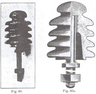
This insulator, it will be observed, is of corrugated form, having four
grooves provided for various sizes of wire. Experience has proved that not only
are the insulating qualities of this insulator of a high order, but, owing to
its peculiar shape, it possesses the virtue of being much less easily broken by
stone throwing than insulators of the more ordinary smooth-faced type, This is
undoubtedly a most desirable quality for an insulator to possess, as it involves
a very great saving in the cost of replacing broken ones, and what this means, in country
districts particularly, can only be fully appreciated by those who have had
practical experience of the enormous destruction and consequent loss caused
in this way.
While this form of insulator has the virtues already ascribed to
it, it has at the same time one great disadvantage which somewhat discounts them. Its many grooves are a
standing and open temptation to the average
lineman to save himself trouble by attaching more than one line to a single
insulator; indeed, the writer has himself not infrequently seen a separate line
fixed in each groove of one of this type of insulator.
The same drawback applies also to the Langdon
insulator, but in a less degree, as it only has three grooves. The effect of this,
particularly in damp weather, is of course obvious, and it is therefore quite unnecessary to dwell
upon the matter. Insulators have
been made of all kinds of material: wood, glass, ebonite, earthenware,
porcelain, etc. It is now however generally agreed that porcelain is superior to
any other description, and it is therefore of this material that all the best insulators
are now made. Well-glazed earthenware is also much used, as not only are its
insulating qualities high, but its colour renders it less liable to breakage by
stone throwing, owing to its not being so conspicuous a target as an insulator
made of a white substance like porcelain.
The quality that is most required in
the material employed for making insulators is, that it shall not be capable of absorbing
moisture. Leakage of current does not take place through the body of an
insulator, but over its surface, through the medium of any moisture that may
settle upon it. A substance which is capable of taking a high degree of polish
is therefore best suited for the purpose, providing of course it is also in
itself a non-conductor, and this quality is possessed by porcelain to a higher
degree than by any other material.
The great advantage obtainable by the use
of an upright insulator is that it contains a practically dry inner surface,
even in the wettest weather, and the larger the area of
this dry inner surface can be made between the groove on the outside in which
the wire to be carried by it will lay, and the insulator bolt, the more
efficient will the insulator be. In order to achieve this object, various forms
of insulator have been designed, consisting of two or more inverted cups, one
fitting over the other, a large area of dry surface being thus obtained,
offering an exceedingly high resistance to the passage of any current from a
line wire attached to such an insulator, to earth, through the bolt and pole.
Insulators of this kind were first made all in one piece, and one of the best
of this type is that known as the "Cordeaux," shown in Figs. 81 and 82,
which has been very extensively used, particularly for the purpose of insulating
long trunk lines in Great Britain.
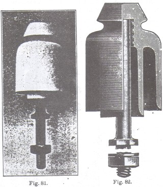
Insulators of this type are technically
known as "double shed," in contradistinction to those composed of one
inverted cup only, such as the" Bennett," which are termed "single shed." On looking at the sketch of the
last mentioned form of insulator, it will be observed that the iron bolt upon
which it is carried is cemented into the cup, whereas in the "Cordeaux" it is screwed in, which is a great advantage, as the
insulator can be taken off the bolt and the inside of the cups easily cleaned,
or should the cup got broken, there is no necessity for the bolt to be renewed
also, which would be necessary in the case of those having fixed bolts.
Various methods are adopted in order to test the quality of different types
of insulators or a number of the same kind. The one most commonly employed is as follows:
-- The insulator cups to be tested are placed in suitable racks fitted inside a
lead-lined trough, which is filled with acidulated water,
with which the insulator cups are also filled, paraffin wax or some similar
substance being smeared round their edges, to prevent the water in them coming
in contact with that in the trough. In this state they are left for about twenty-four
hours, in order that they may receive a thorough soaking.

The lead lining of the trough is then connected to one pole of a powerful electric
battery having its other pole joined to a reflecting galvanometer, the second terminal of
which is connected by a flexible wire to a metal rod provided with an
insulated handle, as depicted in Fig. 83.
The rod is dipped into each separate cup, and if the galvanometer needle is
not deflected when this is done, or is not deflected beyond a. certain point of
known value on its scale, the cup under test is considered as satisfactory, or
if otherwise rejected as unfit for use.
Insulators made either of porcelain or
glazed earthenware are universally employed by all British and European
telephone administrations; but the general practice in the United States is to
use glass for the purpose, although it is far inferior to porcelain as an
insulating medium, a, moisture adheres more readily to it, and being very
brittle it is more easily broken. Its one great recommendation appears to be
that insulators made of it do not harbour insects as much as would insulator
made of a substance through which the sun's rays would not penetrate; and in
a climate such as that of America, which is semitropical for a large part of
the year, this is an important consideration.

Two forms of insulator are
usually employed in America made of moulded glass, one being of the single shed type, and the other of the double shed or
"double
petticoat," as the Americans term it. The small single shed is commonly
known as a "Pony" insulator, and it is used for all ordinary purposes,
and the double petticoat form for terminating (Figs. 84 and 85).
Not only
does American practice differ from that in vogue in Europe so far as the
material of which the insulators employed are made is concerned, but it also differs
in that wooden pins 1-1/2 inches in diameter are generally used instead of iron
bolts to carry the insulators, as they are considered to be stronger, and will
not bend when a heavy stress is placed upon them, as iron bolts will sometimes
do. These insulator pins are usually made of split oak, locust, or cocus wood,
the latter being preferred, as it is stronger than oak, but more expensive.
These pins are painted and nailed into the arm holes with wire nails.
One
disadvantage arising from the use of. the insulators of an upright form, and
which often requires special means to be taken in order to counteract it, is
that when an excessive stress is placed upon one side of them they are apt,
when an ordinary straight bolt is used, to either bend over or twist the arm.
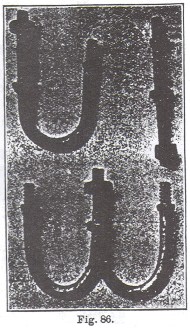
In
order to meet this difficulty various devices have been employed, such as using
bolts with large shoulders bedding on the arm, or an iron washer under the
shoulders; but by far the most effective method, and the one now generally
adopted, is to use bolts of J form after the patterns illustrated in Fig. 86.
This pattern is universally used in Great Britain for terminating purposes,
and also largely on the continent, and has been found very effective.
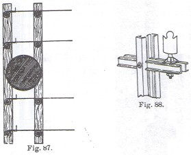
In America the method adopted to counteract the stress on insulator pins is
shown in Fig. 87, in which it will be seen that the pole is double armed. The
line wire is first wrapped round an insulator on the arm nearest to it, and then
taken to another insulator on the back arm, round which it is made off in the usual way. The back insulator and pin thus act as an anchor for staying the
one to which the line wire is first attached on the front arm.
French and
Italian insulators are usually made with earpieces (Fig. 88), the object these
serve being to prevent a wire falling should it break loose from its binding.
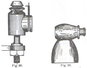
For leading wires into buildings several special forms of insulator have been
devised; one of these, commonly known as a "spur" insulator, is illustrated in Fig. 89.
It
consists simply of an ordinary double shed insulator with a side piece attached,
in which there is a groove, and round this a wire dropped from a roof can be
easily made off without the risk of dragging the insulator out of an upright position. Another pattern of the same type of
leading in insulator much used on the continent is shown in Fig. 90.
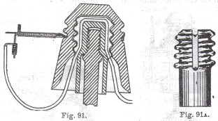
Yet another form of leading in insulator is that shown in Figs. 91 and 91A. In this type the special object
aimed at is to prevent surface leakage by
keeping that part of the covered leading in wire nearest the insulator in a
perfectly dry state. This object is attained by making the insulator in three
separate parts, viz. the bolt, and inner and outer cups. The inner cup is
screwed on to the bolt and the outer cup on to the inner one., At the top of the
inner cup and down its sides a groove is provided, in which the covered leading
in wire is laid before the outer cup is screwed on, thus keeping it perfectly
dry, and preventing the escape of current from the open line wire to earth, through the
medium of a wet covered lead laying on a damp wall or other place connected with the earth.
The lead
should not touch the cups at any other point but at the groove on the inner one.
Most of the types of insulators already described were devised for the purpose
of carrying a much heavier class of wire than that now generally employed for
short local lines, but the use of very light overhead wire makes it unnecessary
to employ such heavy types of insulator. As the size of the wire used has
decreased, experience has proved that the insulator suitable for use with it may
be decreased in size correspondingly also, without injuring to any appreciable
extent the electrical efficiency of the circuit on which such smaller insulators
are employed.
Double shed insulators of small size are now therefore generally
used by all telephone administrations employing a small gauge of line wire; for local
circuits, similar in size
and pattern to that illustrated in Figs. 92 and 92A, which is known as the "Sinclair,"
and is the standard type used by the National Telephone Company for insulating
all local exchange and private lines.

The weight of this insulator and bolt is only 1 lb. 12 oz., while the
Cordeaux insulator and bolt weighs 2 lb. 6 oz., and the original Bennett
2 lb. 10 oz. This large reduction in weight makes it possible to employ
lighter supports in many cases than would otherwise be safe, which is a very
considerable advantage where supports have to be fixed on very lightly made
roofs particularly. A much smaller size of Bennett Insulator is now also being
made which is well suited for use with small gauge wire. It is provided with a
screw instead of a fixed bolt, which is a great improvement on the original
form. Small insulators also have a much neater and less obtrusive appearance
than those of large size, and not the least important advantage they
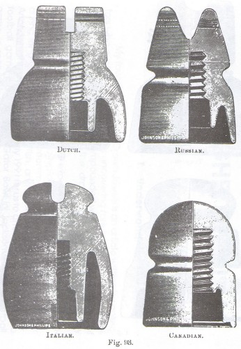
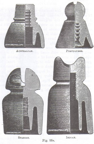
possess is that they are considerably cheaper. Figs: 93, 93A, and 93B
illustrate various standard patterns of insulators employed by continental and
colonial governments.

|

)
)
)
)
)
)
)
)
)
)
)
)
)
)
)